To this day, I have my first FPGA development kit with a Spartan-3 chip on board. I purchased it somewhere around 2004. Those were the days when Xilinx (today an AMD brand) provided the ISE development environment based on TCL scripts.
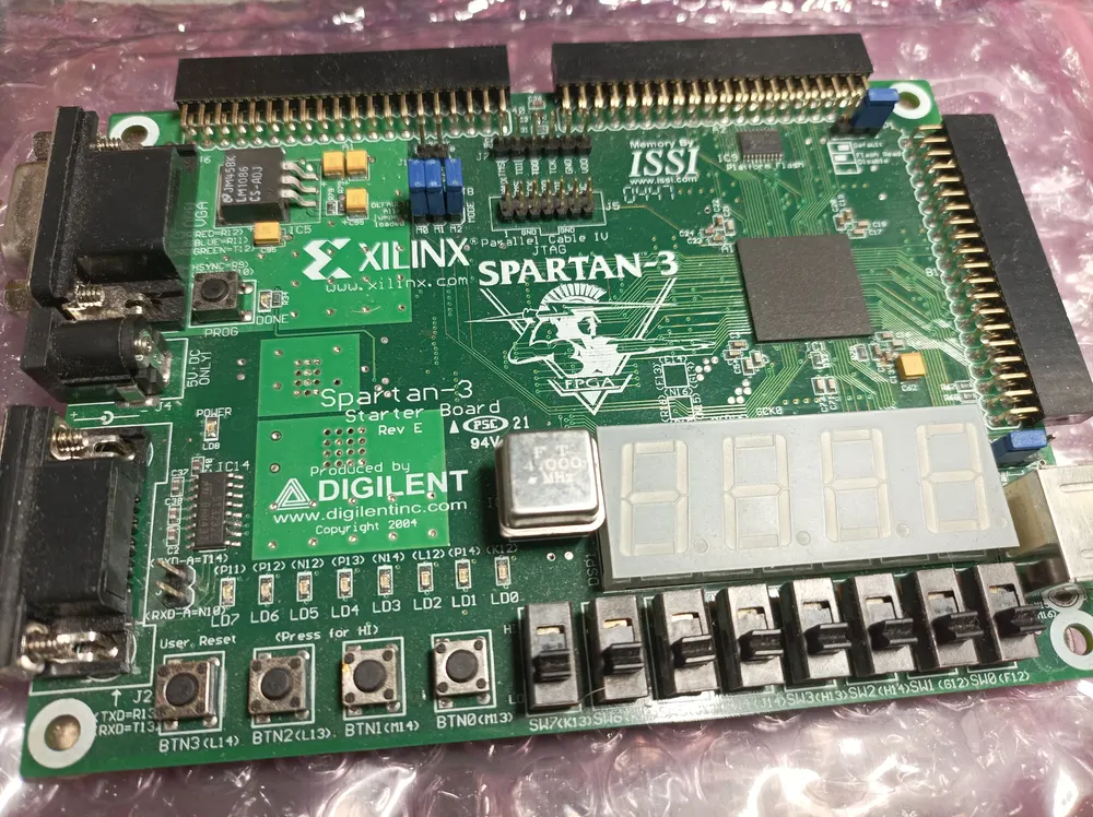
My first Spartan S3 kit from Digilent
Fast forward to 2026. The Spartan-3 chip has passed into history along with the ISE environment, which was replaced by the Vivado/Vitis combo. Through these nearly three decades, lithography technology has changed, enabling the creation of more efficient (in terms of speed and energy) chips. The functionality of the chips has also significantly expanded - it is no longer just FPGA structures with a synthesized MicroBlaze processor - but ready-made System on Chip systems that contain a combination of an ARM processor (PS block) with an FPGA structure (PL block).
The archaism trap
At the time I was buying my first kit with the ISE environment – there were no Dual Core processors on the consumer market yet, as those entered into use in 2005. Working with the ISE environment consisted of linearly running a series of TCL scripts and waiting for the generated bitstream.
Today - as I write this - I am doing it on a computer that can run 20 parallel threads simultaneously. But it does not matter anyway, because the old engine - just like it did nearly thirty years ago - will still linearly run scripts one after another, really rarely going beyond a single thread. The most common explanation encountered today is that “routing space search heuristic algorithms are difficult to parallelize” but sorry, I am not buying that. Since around 2020, there are possibilities to utilize graph libraries for PyTorch (i.e. PyTorch Geometric) and CUDA acceleration. Someone here clearly got stuck in the past.
Case Study
I have a few SmartZynq boards sitting in my lab - and the thing I missed most -was the ability to hook up an external monitor - so I could run Linux with a graphical user interface. Accessing the OS solely through a UART terminal is just a lack of taste.
So, I designed a custom GPU card that utilized about 1/4 of the resources offered by the Zynq chip. Building the entire project took nearly half an hour. Such archaism is honestly embarrassing. Especially considering that when I usually compile code, I just throw in the -j20 flag and listen to my CPU fan rev up to a full speed.
The Options
The fastest workaround is to simply accept the status quo and assume that’s just how things are. You sit there, staring at the monitor, waiting for the results. If something goes sideways, a single day gives you a time window for maybe a few iterations of design tweaks followed by another round of synthesis and implementation. For me, this is out of the question - it’s just a counterproductive waste of massive amounts of time. I’ve heard rumors that paying for Enterprise license makes things better, but I would’t expect miracles.
I can’t change the software solution AMD forces on us, but I also refuse to spend hours staring at a progress bar waiting for a bitstream. What I felt I needed to do was delegate this tedious, repetitive task to an employee who could oversee the process for me. And finding such a worker - especially in the era of AI agents - shouldn’t be that hard.
Local Agentic AI
The easiest route would be to pull out a fat wallet, throw money at the table, and -completely disregarding the confidentiality of data and projects - pay for a flagship commercial model and call it a day.
But that approach goes against my grain. First of all, I have no intention of getting hooked on tokens that are pushed like street drugs: the first dose is always free. Secondly, I know exactly how valuable the know-how buried inside proprietary hardware designs can be. I see no reason to tokenize it and ship it off into the cloud to models where no one knows how it’s being processed (whether it’s for reinforcement learning or outright industrial espionage). For these reasons, I knew the system had to run locally.
Choosing the AI Model
Another shortcut would be allocating a massive budget to buy a bunch of DGX Spark or Halo Box clusters to serve inferences from the heaviest possible model for local Agentic AI. But that’s more than lame.
I did it differently. At the very beginning, I set-up a quick agentic AI environment using Goose. Its task was to handle the entire project cycle until a bitstream was generated. The variable in this equation was the model variant, and the goal was not actually to get the bitstream, but to find which model seemed to grasp the assigned task most accurately.
Since I care about efficiency, I selected strictly lightweight models for the benchmark and watched their actions unfold on screen. Some models did slightly better than others, while some were completely lost. However, the common denominator was that their primary actions consisted of trying to understand what the project actually was and how to execute the task. The models listed directories, guessed which file did what, and tried to figure out what to do next based on the reasoning within their core knowledge. I could see they were trying to move in the right direction, but way too much time was being wasted on empty inferences and guessing games.
MCP is the Foundation
You can think of MCP (Model Context Protocol) as a Swiss Army knife or a multitool that we hand to our agent before it goes to work.
For example, it was obvious that the agent was trying to figure out the project entirely on its own. But by utilizing MCP, we can give the agent exactly what it needs:
Listend bud, here is a library. This shelf labeled “TCL” contains a TCL scripting manual and the documentation for using TCL syntax in Vitis/Vivado. The next shelf holds the complete Verilog and VHDL standard specifications. If you need anything, here is a search function - use it to scan the library documents for specific phrases.
My first tool provided via MCP fundamentally changed the agent’s behavior. The model stopped guessing and trying to deduce what the project was. Instead, it seamlessly browsed the relevant, hard-solid sections of the manuals whenever it hit a snag.
In previous article series I described my experiment with building a RAG systems. Based on that experience, I kept wondering how a RAG solution (foundation of a library tool) should be implemented. Especially when FPGA documentation is loaded with tables, block diagrams - and structural layouts where converting them into raw tokenized text completely breaks the formatting and destroys the context.
clever RAG setup
I decided to go with a clever mechanism using a so-called inverted native index. How does this work in practice? The documentation was split page by page, embedded, and fed into a vector database.
-
When starting a search, the agent passes the “shelf name” and the target search phrase to the MCP.
-
The MCP mechanism searches for the closest vector using cosine similarity and ranks the results (also grabbing the previous and next pages just in case a topic happens to split across two pages). The agent receives a clean table pointing to the page numbers and their ranking scores.
-
Next, the agent uses a page-reading tool that looks directly into the PDF document, returning the page completely intact, exactly as it appears in reality (lossless).
On top of that, I threw in a few auxiliary functions - like browsing the table of contents of a given document. The effect? Absolutely incredible.
Time Boost: It’s a joy to watch an agent equipped with this tool hit the exact information it needs and apply it immediately, rather than spinning up wild theories and testing them through trial and error - which would otherwise burn massive amounts of time and compute energy. And that guessing cycle would repeat every single time the agent boots up with an empty context and has to rediscover what the project is.
Quality Boost: The results are staggering - the exact same model using MCP never generated syntactically incorrect Verilog/VHDL code, a mistake it always made when relying solely on its self-reasoning. Not to mention that in the latter case, it meant repeatedly running Xilinx tools only to eventually find out that Roses are red, Violets are blue, Unexpected ‘{’ on line 32.
Expanding the MCP
At this point, it’s worth noting that LLMs are vastly better at pattern association than actual deep reasoning. What I mean by this is that you can’t just give a model the full C language spec and compiler flags, expect it to read, comprehend, and memorize it all, and then tell it to “go code” and watch it write software from scratch.
It is much easier for a model to look at 10 existing C programs and use them as a reference to write the specific program you actually want. That’s why a raw documentation library in MCP is nowhere near enough if you want your agent to handle complex tasks. Since setting up code repositories right next to your documentation shelves is quite straightforward, expanding my MCP in this direction was a no-brainer.
As a side note—while writing your own MCP, I highly recommend building test runners for every single MCP function right out of the gate. This allows you to quickly and easily benchmark how your setup performs across different model variants, embeddings or ranking configurations.
Model Choice and Quantization Levels
With the right boost, lightweight models can easily match the performance and quality of much heavier ones. They can run on absolute “potato” hardware and don’t require massive investments in inference infrastructure. I won’t lie - watching your own little patch of “potatoes” pull off these tasks is incredibly satisfying.
But practically speaking: which model should you choose? After running your initial tests with the agent and MCP, you should have a rough idea of what your target model looks like. I can’t give a one-name-fits-all answer because everyone has different VRAM constraints. In my setup, GLM 4.3 Flash performed the best. It’s fast, well-reasoning, and handles MCP tools with the most agility.
However, that’s not the whole story. Models hosted on Hugging Face are typically saved in the SafeTensors format. From there, you convert them to GGUF format with an appropriate level of quantization. Simply put, quantization determines how the weights that pass information between model layers are stored. These weights can be stored in bit-size strings of varying lengths. For instance, if you use a model quantized to Q4, the weights are 4 bits in size. For Q8, the flags will be twice as large—8 bits. The larger the weights, the higher the precision - but you also need significantly more VRAM to load the model and inference speeds slow down accordingly.
This opens up another playground for benchmarking. In my experience, the ultra - lightweight Q4 version worked perfectly fine for standard everyday tasks, whereas the Q8 version wrote visibly better RTL code. But unfortunately, neither version was completely flawless.
A Flawed Benchmark
While reading Kevin Hubbard’s book Mastering FPGA Chip Design: For Speed, Area, Power, and Reliability (highly recommended for reading if you’re still stuck answering what makes transistor runs the code), I stumbled upon an entertaining paragraph in the RAM chapter. It mentioned that writing a fully functioning, robust FIFO block from scratch is notoriously tricky - and it’s almost always better to use pre-built, verified library modules instead. This inspired me to make the creation of a FIFO block the ultimate benchmark task for the model.
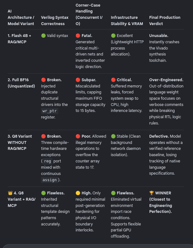
GLM 4.3 Flash coding FIFO module
While the models using MCP consistently spat out syntactically flawless code that compiled without a hitch, the architecture itself suffered from more or less severe flaws. For example, the model would obsess over the handshake logic for control signals while completely leaving the data bus floating in mid-air—which the Xilinx synthesis tools just quietly tied to ground. If you let an agent blindly iterate on code like this inside archaic EDA tools, it could easily take days before a proper FIFO block actually emerged. This simply confirmed an old truth as old as AI itself: all models are wrong, but some are useful.
What’s Next?
Do we just cross our fingers and hope the agent eventually “guesses” right on the next iteration? And what does “getting it right” even mean when the code is syntactically perfect and doesn’t break the bitstream build…? Are we going to let the model invent its own testbench vectors and become the iure in causa sua…?
These are excellent questions, but we undeniably need to steer towards obtaining the best possible model. Building and training a proprietary AI model from scratch makes absolutely zero sense these days. A far superior approach is fine-tuning an existing model - in our case - specifically for writing RTL code. And I am almost certain that this is the exact route taken by anyone offering expensive, custom-quoted AI models for FPGA/SoC programming.
Model Fine-Tuning
Once you know which model fits your pipeline, there’s nothing stopping you from “tweaking” its neural network so that it interacts better with RTL code. At least, there’s no problem in theory. The golden rule of GIGO (Garbage In - Garbage Out) stands: if you train or fine-tune a model on garbage data, you will end up with a garbage model.
Fundamentally, model training relies on a dataset of X/Y pairs, where X represents the instruction given to the model, and Y represents the expected output. Sounds simple enough, but as always, the devil is in the details:
Task X cannot be too generic: you can’t just feed the model an instruction like “write Verilog code for a 16-byte FIFO.” That command is far too vague. It needs to contain every single technical specification the model needs to know exactly what to generate.
Output Y (responding to command X) must be deterministic. The moment there are multiple equally valid ways to write the code, the specific snippet in your training sample ceases to be a reliable metric for a successfully completed task.
My current strategy - which I am actively implementing right now -is to use the same GLM to analyze existing, verified RTL code. Based on that analysis, it reverses the process: it generates a training sample where X contains all the absolute necessary data needed to cleanly produce output Y.
Here is an example sample:
X: Generate a synthesizable Verilog module that perfectly satisfies the functional description and adheres strictly to the target module interface signature provided below.
Functional Description:
6-bit Shift Register LUT with Carry
Target Interface Signature:
module SRLC16 (Q, Q15, A0, A1, A2, A3, CLK, D);
Verilog Code:"
Y:
`timescale  100 ps / 10 ps
module SRLC16 (Q, Q15, A0, A1, A2, A3, CLK, D);
parameter INIT = 16'h0000;
output Q, Q15;
input  A0, A1, A2, A3, CLK, D;
reg  [5:0]  count;
reg  [15:0] data;
wire [3:0]  addr;
wire    q_int;
buf b_a3 (addr[3], A3);
buf b_a2 (addr[2], A2);
buf b_a1 (addr[1], A1);
buf b_a0 (addr[0], A0);
assign Q = data[addr];
assign Q15 = data[15];

initial begin
    for (count = 0; count < 16; count = count + 1)
    data[count] <= INIT[count];
end
always @(posedge CLK) begin
    {data[15:0]} <= {data[14:0], D};
end
endmodule
We have to be incredibly selective about the code we choose for fine-tuning to avoid degrading the model’s general capabilities. Let’s be honest - not every piece of code can be neatly compressed into a functional description that cleanly expands back into a single, deterministic Y output. How do you describe a MicroBlaze processor in a few sentences…? You can’t. It’s nonsense - and those kinds of samples must be discarded immediately.
How do you sort these samples properly? I concluded that the best way is to use an LLM whose sole job is to evaluate the code and determine whether it can be assigned a description tight enough to yield a definitive Y result. This is by no means a fast process - preparing a massive dataset this way takes a significant amount of time - but it’s likely the only logical approach that can be fully automated.
Looking at this example sample, and particularly at the output, I get the distinct feeling that during the actual training phase, we won’t get away without using an LLM to evaluate the outputs analytically either. After all, who is to say the model won’t name a wire buf b_var0 instead of buf b_a0 while keeping the logic identical? We will have to tackle functional and analytical code validation rather than just checking raw semantics with Python script.
By the way - if it crossed your mind to use one of the commercial flagship models to generate and verify these fine-tuning samples, as well as evaluate the outputs during the training process… congratulations! You just conceptualized model distillation.
Since these datasets are going to take a while to crunch through my pipeline, I think this is the perfect place to put a pin in it and split this article into two parts.