For years I’ve been using Microchip’s official Real ICE in-circuit emulator for programming and debugging PIC processors. Then Murphy’s Law struck while I had to download firmware to a fresh batch of boards - something went wrong, and I didn’t even know it yet.
After a few failed attempts, I discovered to my surprise that Microchip had dropped support for the Real ICE in MPLAB X IDE version 6.25 and newer. So now this rather expensive but perfectly functional tool can sit on the shelf and look pretty.
How to keep using the Real ICE anyway?
I don’t need to tell you I was pissed. An entire batch of devices is waiting to be programmed, and Microchip’s solution is “just spend another $500 on the new model”. In a hurry, I spun up a virtual machine and installed MPLAB X v6.20.
If you’re looking for older versions of the tools, you can find them at: https://www.microchip.com/en-us/tools-resources/archives/mplab-ecosystem
It works in practice, but you can’t update the software anymore — otherwise the Real ICE stops working. This approach is fine for maintaining legacy projects, but you have to accept that you’re cutting yourself off from updates, including support for newer processors that might come in the future. It’s a very temporary band-aid.
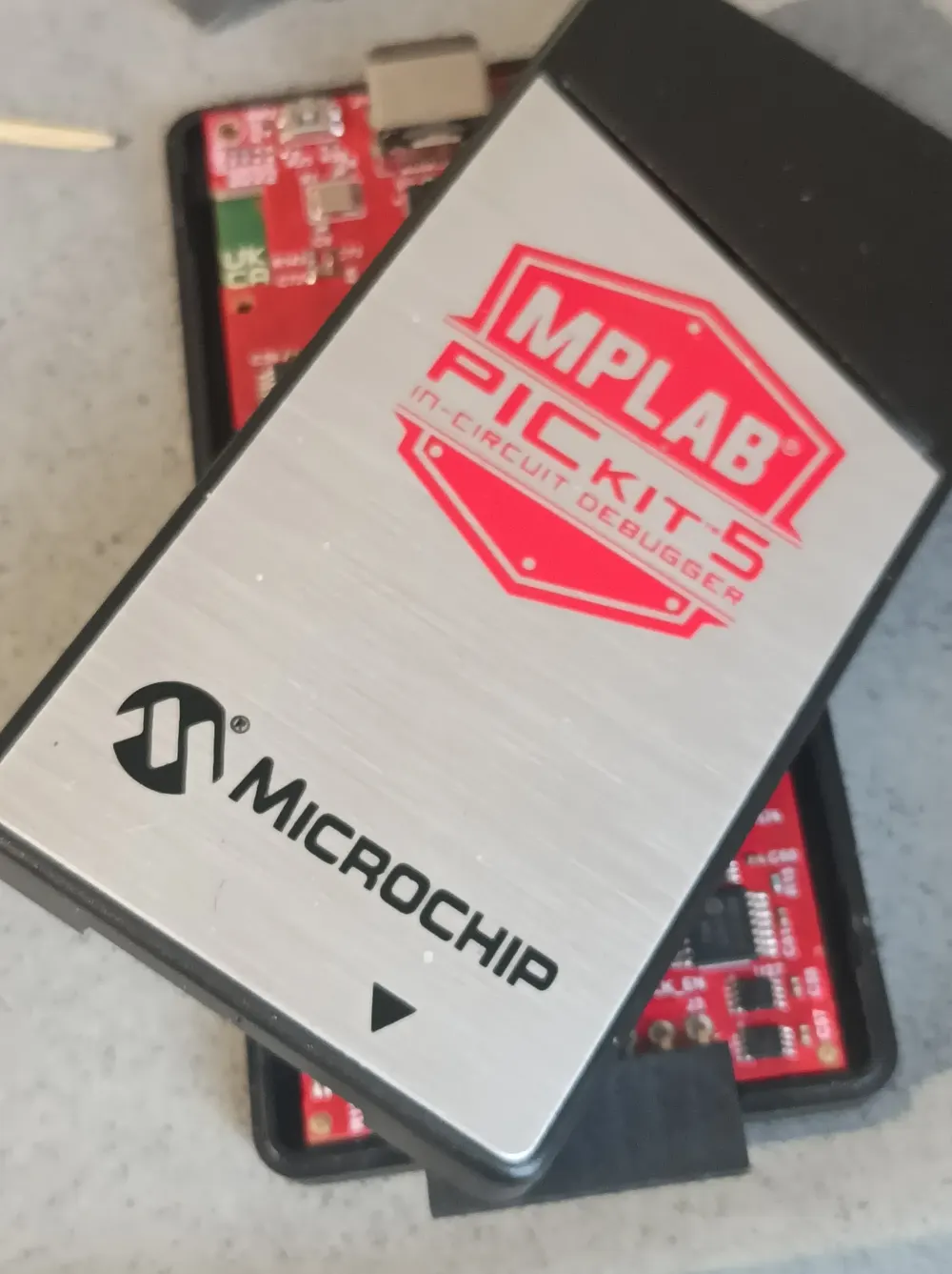
PICkit 5
I didn’t like what Microchip did - killing off a perfectly good tool and expecting me to pay for a replacement. The cup of bitterness overflowed. I decided it was time to abandon Microchip in favor of ST Microelectronics. As a stopgap, I bought an original PICkit 5.
PICKit 5
After two or three weeks, I managed to brick it. One moment of inattention — wrong programming cable that didn’t match the target board. Nothing smoked, no fireworks, but the programmer stopped detecting the device ID. Over the years with the Real ICE, I’d made plenty of mistakes too, but nothing ever broke. I started digging for information and quickly learned that if you have Hardware Revision 3, you’re in pretty good company — a lot of people have had their PICkit 5 suddenly refuse to work. Some folks buy them in bulk because they fail so often.
Honestly, this only reinforces my decision to switch to ST Microelectronics. Their programmers cost about 1/10th the price, and so far none have died on me. If one does, I can just throw it in the bin without crying. And last but not least - hopefully this write-up saves someone else from throwing money at a new one.
Reverse Engineering
One of my personal flaws is trying to fix everything around me. The upside is you learn a lot; the downside is you never have enough time, and eventually your workshop turns into a junkyard.
Partially reversed PCB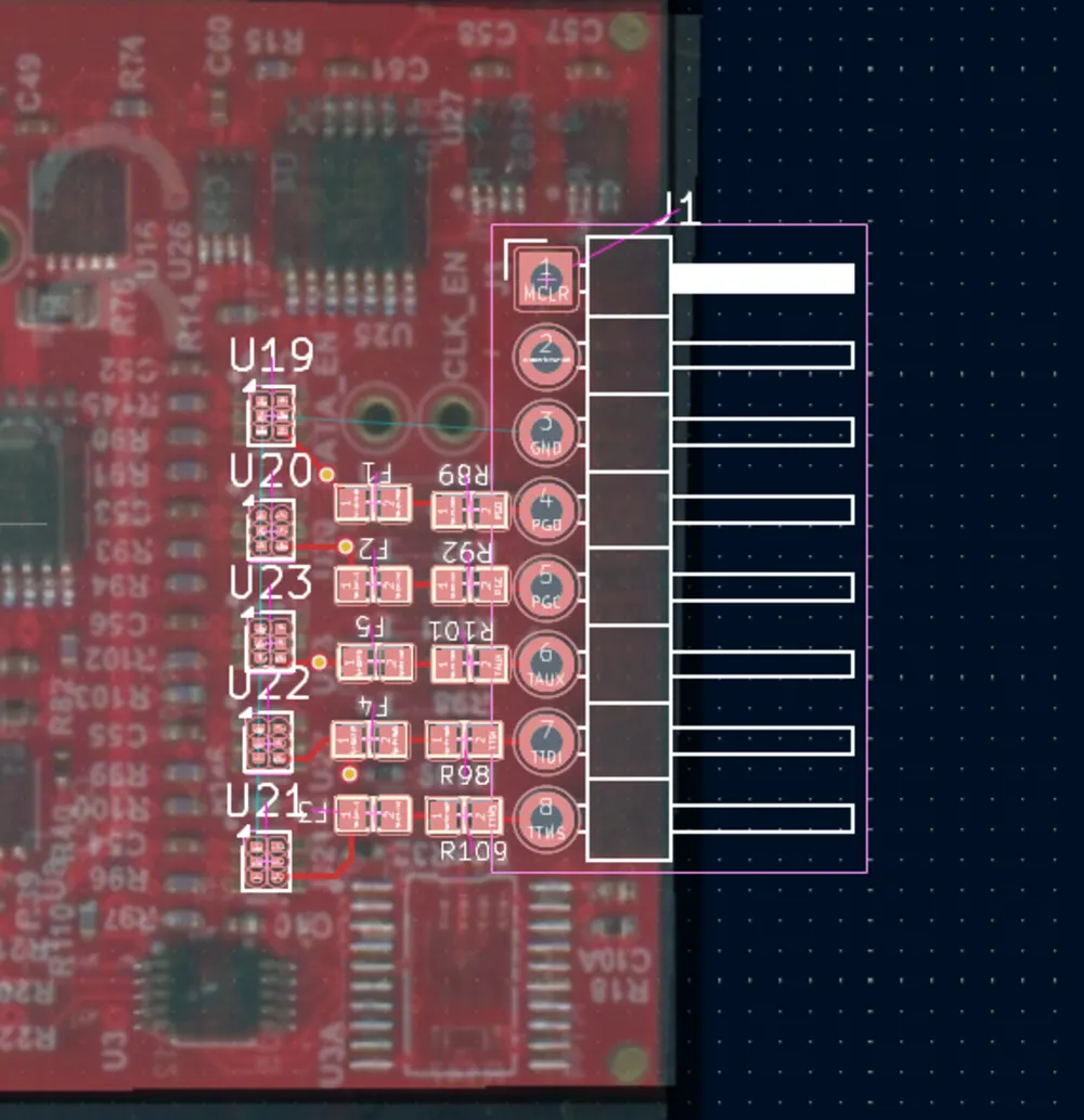
First step: open the case. The best tool for this is a guitar pick.
I reverse-engineered the schematic. The key components in this programmer are the 74LVC1T45 buffers with SMT marking “V5” (transceivers) on the signal lines.

PICKit 5 input circuit diagram
If the image isn’t readible, here’s the PDF version.
Troubleshooting
Here’s what and how to check.
Lines Between the programming connector and the “B” side of the transceivers
On these lines you’ll find series 22Ω resistors, a polymeric fuse, and a TVS diode (on the bottom of the board):
-
from the programming connector to pin 4 of the consecutive transceiver, you should measure 22Ω. If not, check the fuses and resistors (in my case, for example, a track between PGD and R89 was burned — somewhere on an inner PCB layer).
-
check the resistance of each line to the ground — just in case one of the TVS diodes has shorted.
VCCA / VCCB Voltages
VCCA comes from the processor’s power supply circuit. Honestly, I didn’t even bother checking it - it’s just there. Measured value: 3.3V.
The interesting part is VCCB. I assumed it would be powered from pin 2 of the programming connector (Target VDD). Turns out .. there’s still 3.3V on VCCB even with the target board disconnected. I suspect this pin is also supplied (perhaps through a diode from some 3.3V DC/DC converter), and when you connect real Target VDD the diode goes into reverse bias… However: in my case, Target VDD is not connected to VCCB at all.
Transceiver Operation
Connect a DSO or logic analyzer. Whether the transmission is going out from the PICkit 5 (A→B) or coming in (B→A, controlled by the DIR bit), you should see identical waveforms on both I/O pins of the chip (possibly with different amplitudes matching the logic levels).
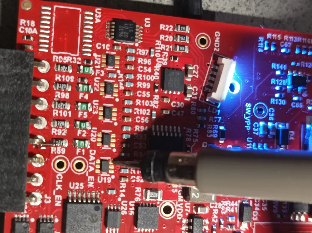
Probing traces with DSO
Launch MPLAB and try to program something. Check for activity on pin 3 (I/O A) and pin 4 (I/O B) of the transceivers U19-U21. If you have a signal on only one side - the chip is dead. In my case, U20 died. I had a clean signal on I/O A but complete silence on I/O B.
Testing traces on A/B ports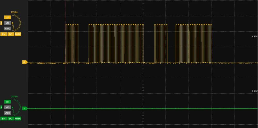
Repair
Components
For the repair you’ll usually need to buy a handful of transceivers. The originals are in BGA packages and not every supplier stocks them, but the good news is that Microchip designed the board so that TSSOP8 versions also fit perfectly. My supplier had 74LVC1T45GM-Q100X that is a 100% match to the existing ones.
Replacing the Chips
You’ll need two tools: an infrared preheater to warm the whole board to around 160°C first, and a hot air station to remove the faulty transceiver.
Pro tip: When removing the chip, place the new one on the PCB right away. This way it’s already pre-heated and you’ll minimize the actual soldering time.
WARNING: Do not move the board until it has fully cooled down.
A true story from the front lines: my friend worked in a phone repair shop. One afternoon he decided to change a chip on his own device. He preheated the board with hot air, lifted the dead IC, placed the new one, and then proudly picked up the board to admire his work.
His eyes immediately fell on a suspiciously tidy collection of SMD components neatly arranged on the bench in front of him. For half a second he wondered who the hell left their parts there… until it dawned on him: those were all the parts that had dropped off the bottom side of the board.
Blood pressure through the roof. “Okay, no big deal,” he thought, “I’ll just put them back.” But first - he needed to cool down, so he went out for a cigarette. While he was gone, a coworker came by, needed space on the bench, and with one sweeping motion brushed all those “useless little bits of garbage” straight into the bin. Moral of the story? Let the board cool completely. Always.
I would advise against using the popular MH30 preheater. Why? Because it doesn’t contact PCB but heats the bottom-layer components first. The plastic packages of the TVS diodes are poor heat conductors, so you’ll nicely cook the board before the solder on the top side even melts.
aftermath
I finally got around to finishing the repair. Here’s exactly what I did:
- I soldered a thin wire bridge between R89 and the programming connector pin - the original track had burned out somewhere deep inside the multilayer PCB
- then I replaced the obviously dead U20 (I knew from the timing that this one was toast). Still no change. Just to be safe, I also swapped U19.
At this point I was starting to scratch my head. I decided to double-check that the new transceivers were actually working properly, so I put the scope on the A and B sides. The signals looked perfect — clean, properly timed, and bidirectional on both chips:
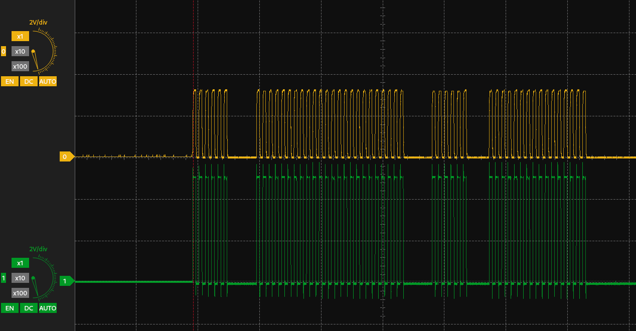
Testing traces on A/B ports
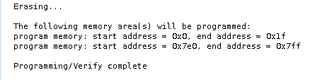
Everything on the transceiver side was perfectly working as it should. So what the hell was still wrong? Turns out the last thing standing between me and a working programmer was a simple firmware recovery. I assume the dongle has stored the hardware error in its own EEPROM memory until the firmware is re-flashed over again.
Pro tip: To flash the recovery firmware, go to “Debug → Hardware Tool Emergency Boot Firmware Recovery” in MPLAB X.
I crossed my fingers, hit the button… and the PICkit 5 came back to life! It now detects devices again, programs without issues, and behaves exactly like before the accident. Mission accomplished.
Now, that’s what I was looking for
This is how it looks after the repair:
Photo of my PICkit 5 brought back to life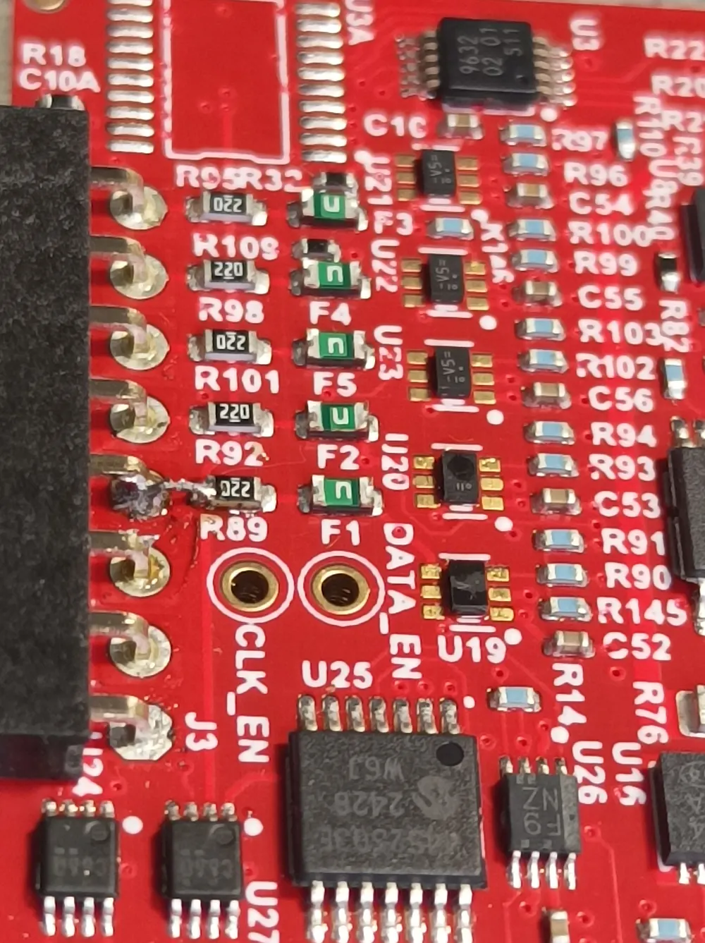
In the end, the total cost of both transceivers was less than $1. The biggest expense was actually the time I spent reverse-engineering the critical part of the schematic needed for accurate troubleshooting and repair. Sure, if this was just a one-off fix, the hours I put in probably weren’t worth it compared to simply buying a new PICkit 5. But because of that effort, I can now share this knowledge with you. If this guide helped you bring your PICkit 5 back to life, I’d really appreciate it if you dropped a comment below and let me know. It always makes the time spent worth it.